Workbook values are tangent / curve spacing; the tangent value is used for the three markers outside each end.
Speed difference
On curve
Before / after
0 mph
50 ft
100 ft
5, 10, 15, 20, 25, or 30 mph
25 ft
50 ft
Only the speed differences listed in the workbook are selectable. Each station counts as one physical marker, including PC and PT. The last curve interval may be shorter than the selected spacing.
The estimate follows the “Existing RCOC unwritten” column in RPM Spacing.xlsx, Sheet1!Q26:R33. The adjacent “Andy proposed” column and archived curvature guidance are separate methods and do not affect these totals.
Workbook placement note: Sheet1!Q34 calls for three RPMs before PC and after PT. The estimate places them at one, two, and three approach-spacing intervals outside each end. Curve markers at PC and PT are included separately.
Spacing stays constant within the curve, with a step to the approach spacing. The workbook’s separate five-second tangent calculation is not added to the three-marker allowance. The optional five-second advance treatment for supplemental centerline RPMs is described in MUTCD §3B.16 ¶04.
Archived curvature guidance — information only
The highlighted excerpt in the workbook is from FHWA-RD-97-152 (1998). Its 80 / 40 / 20 ft values use N = 40 ft. The curvature bands and two-marker rule shown here do not drive the RCOC workbook estimate.
Original workbook image, for reference only. Click to enlarge.Other MUTCD applications — information only
Browse the provisions and diagrams here. Your curve estimate above stays in place.
RPM provisions: MUTCD 11th Edition with Revision 1. Fixed broken-line cycle: MDOT PAVE-905-E. Checked September 14, 2026.
Standard identifies a requirement. Guidance is a recommended practice. Option is a permitted treatment. A numerical check does not establish overall compliance.
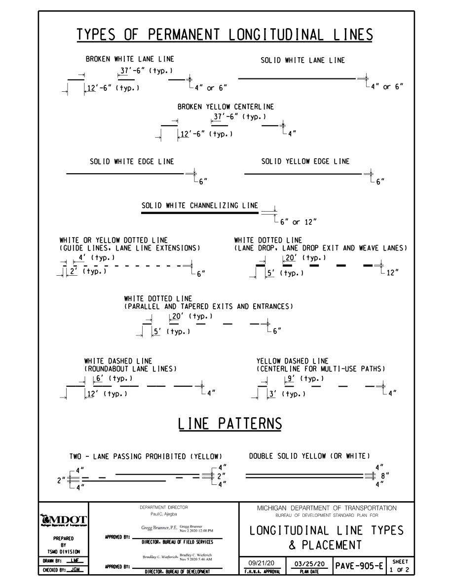
Michigan broken-line pattern
PAVE-905-E, sheet 1: a 12′-6″ dash and 37′-6″ gap for broken white lane lines and broken yellow centerlines. The full cycle is 50 ft. Dotted lines and other special patterns have separate dimensions on the sheet.
Michigan projects: the fixed broken-line cycle follows PAVE-905-E. The federal RPM provisions above are references; the estimate follows the workbook’s “Existing RCOC unwritten” speed-difference table. Also use the adopted Michigan MUTCD and applicable agency plans and specifications. This is not a complete Michigan or RCOC project review. MDOT: 2025 MMUTCD and Michigan changes.
View Michigan line patterns — PAVE-905-E
Sheet 1 shows the 12.5 ft dash and 37.5 ft gap used for the fixed broken-line cycle. Plan date March 25, 2020; FHWA approval September 21, 2020. Click to enlarge.
MDOT PAVE-905-E · Longitudinal Line Types & Placement · Sheet 1 of 2
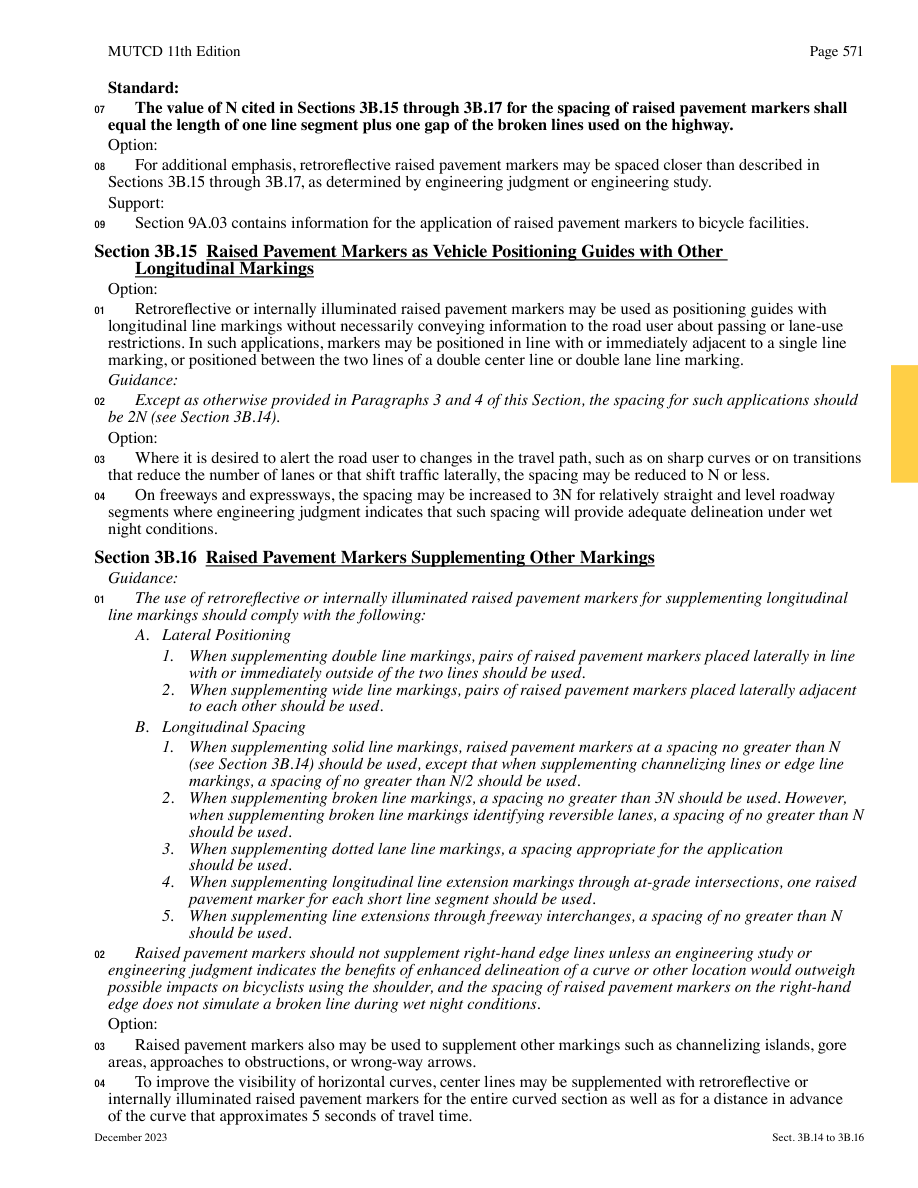
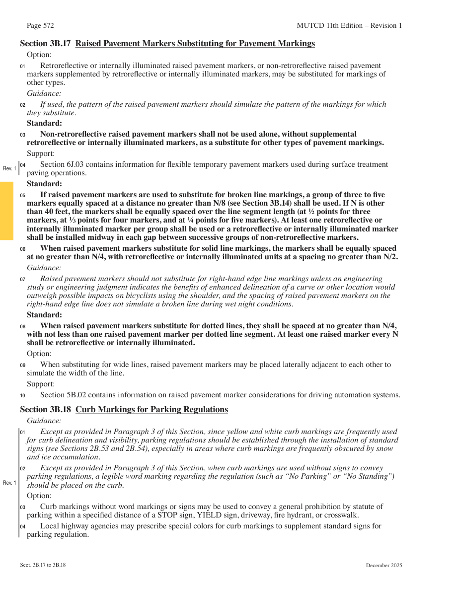
View the official RPM pages
Rendered from the current FHWA PDF. Click to enlarge. Printed page 571 retains its December 2023 date within Revision 1; page 572 includes the December 2025 revisions.
Printed page 571 · PDF page 612Printed page 572 · PDF page 613
Permanent longitudinal layouts only. Temporary flexible markers, wrong-way arrows, bicycle facilities, and special island layouts require their own provisions and are not estimated here.